
In my previous deep dives, I learned how a Time Domain Reflectometer (TDR) acts like ‘radar’ for cables..sending a pulse and listening for the echo to find solder defects or impedance mismatches. But the NVL72 rack doesn’t run on single wires; it runs on Differential Pairs (Positive and Negative signals working together).
My latest training, ‘Beyond the TDR’ with Dr. Eric Bogatin, taught me that looking at just one line is like trying to judge a three-legged race by watching only one runner. To truly characterize high-speed interconnects, we need to move from 1-Port TDR to 4-Port S-Parameters viewed in the time domain.
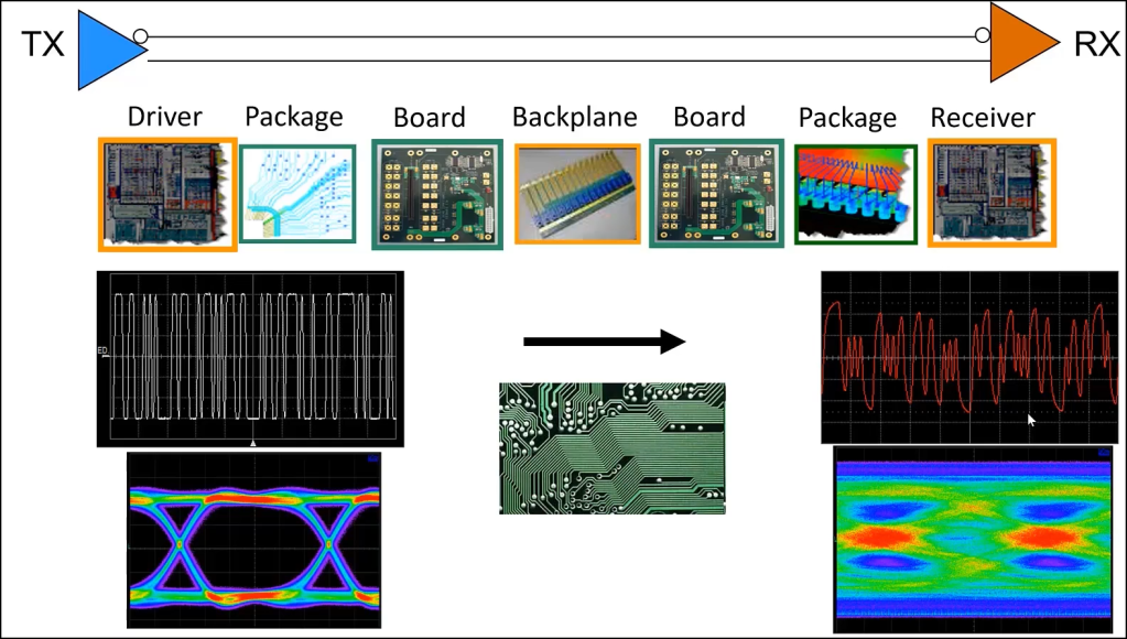
The author explains tell the story of what happens to the data as it travels through the hardware in the first slide.
- Left Side (TX – Transmitter):
- Top Graph: This is the digital signal leaving the chip. It is a clean, sharp “Square Wave.” The 0s are clearly down, and the 1s are clearly up. The transitions are instant.
- Bottom Graph (Eye Diagram): This is the “Eye” of the signal. Notice the big, wide-open black diamond shape in the center. This means the signal is perfect and easy to read.
- Right Side (RX – Receiver):
- Top Graph: This is what arrives at the other end. The clean square wave looks like a messy, squiggly sine wave. The sharp edges are gone, and the height (amplitude) is crushed.
- Bottom Graph (Eye Diagram): The “Eye” is almost completely shut (the black center is tiny or gone). The colors are smeared together.

Leave a comment