
By combining my IPC knowledge (physical fabrication) with Infiniband/MLX (logical/protocol), I have both ends of the spectrum covered. The missing link in the middle is the physics layer. Through next couple of trainings, I will be learning the physics of the specific cables an SQE will be managing.

Twinaxial cable is the superior choice for high-speed applications (like the 50GHz+ signals in an NVL72 rack). Note: The conductors are silver plated, the outer shield is not silver plated.
The Twinax cable comes with a challenges if its own. Imagine a three legged race where you and your partner are tied together at the ankle, it is called a differential pair. The goal is to cross the finish line at the exact same time for the judge (receiver) to record time accurately. Intra pair skew is what happens if one of you runs slightly faster or slower. In NVL72 system, if the signals dont arrive at the same time, GPU cannot understand the message.
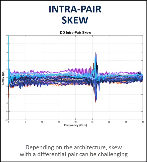
Intra-Pair Skew is the time delay difference between the two wires in a single Twinax pair. The signal on the Positive wire and the Negative wire travel at the exact same speed and arrive perfectly aligned. What could cause the skew? Some of the reasons could be below:
- Physical Length (The “Bend”): If a Twinax cable is bent tightly around a corner in the rack, the wire on the outside of the turn has to travel a longer distance than the wire on the inside.Result: The outside signal arrives late -> Skew.
- Dielectric Variation (The “Bubble”): If the manufacturing process for the insulation (FEP foam) is bad, one wire might have slightly denser foam than the other.Result: The signal in the dense foam travels slower -> Skew.
The second known challenge comes at the transition phase from/to PCB. This exact physical spot where the signal jumps off of the flat circuit board and enters the round wire of the cable.
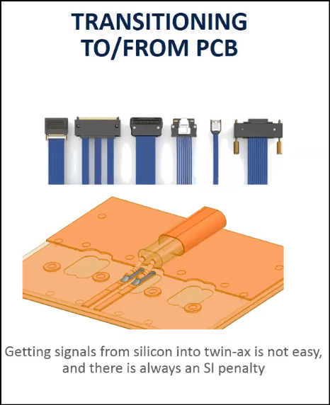
The “Penalty” here refers to Signal Reflection (Echo). In Physics, signals love consistency. As long as the road looks same, signals travels perfectly. However, at the “Launch”, everything changes instantly:
- Shape Change: The signal goes from flat rectangular (PCB trace) to a round circle (wire)
- Material Change: It goes from traveling through fiberglass/resin to traveling through plastic/air
- Space Change: The distance between the ground and the signal shifts.
As an SQE, When you audit a supplier, or look at the failure report, we see a spike in return loss (reflection) right at the connector start point. A good supplier keeps penalty small (eg -15dB reflection). They design the “Launch” carefully so the transition is smooth. A bad supplier has huge penalty (eg -5dB reflection), this happens when they use too much solder or have a gap between connector and the board.
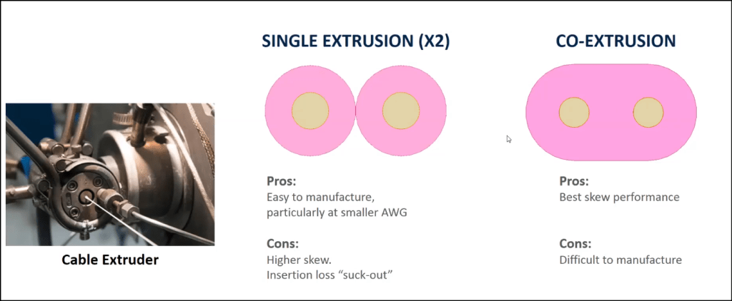
There are 2 types of constructions for creating insulation around twinax conductors. High performance NVLInk cables often rely on Co-Extrusion to ensure the skew stays low enough for high speed signals.
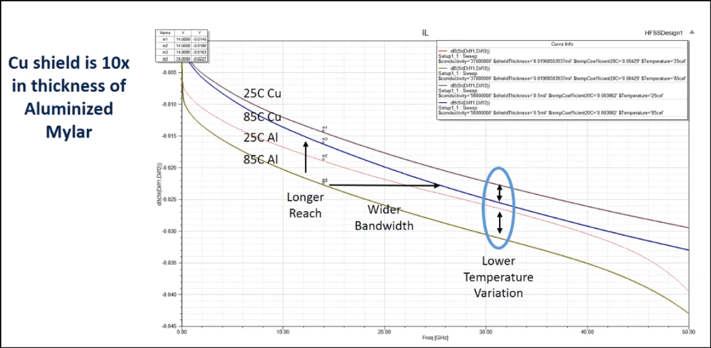
The above chart is a battle between 2 materials used for cable shield 9the foil wrapping that protects the signal): Copper (Cu) vs Aluminum (Al). The graph is indicating that copper is the superior choice for high speed cables like those in NVL72. It has several benefits like Longer reach (extra length), Wider bandwidth (handles high frequencies), Lower temperature variation (stable and reliable even when it gets hot). For an SQE if a supplier tries to sell cheaper cables with “Aluminum Mylar” shielding for a 50GHz application, this chart is the answer to say “No, the insertion loss is too high, we need copper warp for the reach and thermal stability”
So the summary for this lesson is: To guarantee NVL72 performance, one must audit suppliers for stable physical construction, requiring FEP dielectrics and copper shielding while rejecting inferior materials that fail at high frequencies or operating temperatures. We must also validate manufacturing process of co-extrusion and helical wrapping to minimize intra-pair skew. All these dots can be connected when verifying digital health at PCB “Launch” Point, where poor termination creates impedance mismatches.
